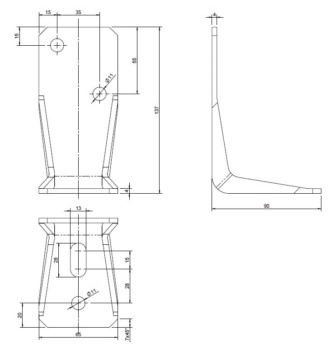
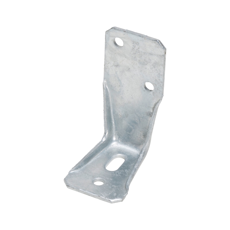
Angle bracket type V-MH with slotted hole
Angle connector type V-MH
ANGL-WOCON-(V-MH)-(TZN)-65X90X137X4MM
Art.-no. 0681632101
EAN 4045989620029
Price for selected packaging unit

Exclusively for trade customers
Register now and access more than 125,000 products
Special reinforced angle connector for load-bearing wood/steel and wood/concrete joints for base anchorage of solid wooden walls in timber structures. Optimal positioning of the angle during assembly thanks to the slot in the foot plate.
- Ideal for use with solid wooden wall constructions thanks to simple screw fastening
- Very high load-bearing capacities
- Sheet metal hot-dip galvanised on both sides (D11 + Z275) in line with EN 10111:1998, thickness 4 mm with subsequent thermal hot-dip galvanisation (55 µm)
- Application in utilisation classes 1, 2 and 3 in line with EN 1995:2013
Proof of Performance
ETA-14/0274
Notice
The general requirements of ETA-14/0274 must be observed.
The general requirements of the applicable anchor approval must be observed.
Product information
Datasheets(X)
Application area
Tension anchor connection of solid wooden walls, supports or purlins to wood, concrete or steel substrates.
Instructions
Suitable fasteners:
- ASSY 3.0 post support bracket screw d =10 mm, ASSY 3.0 combination screw d = 10 mm, ASSY plus VG combination screw d = 10 mm
- Recommended dowels for fixing to concrete d = 10 or 12 mm: W-BS; W-FAZ; W-VIZ; WIT-VM 250
 | |
Width x height x depth | 65.0 x 137.0 x 90 mm |
Thickness | 4.0 mm |
Number of D 11 mm holes in main carrier nH | 1 PCS |
Number of D 11 mm holes in subcarrier nJ + main carrier nH | 2 + 1 PCS |
Elongated hole length/ elongated hole width | 28 x 13 mm |
Approval | ETA-08/0214 |
Product weight (per item) | 422.119 g |
Material | Steel |
Surface | Hot dip galvanized |
Weight | 445 g |
Material designation | DD11 |
Number of D 11 mm holes | 3 PCS |
| Load capacity tables angle bracket V slotted/round hole and V-MH | |||||||||
| Characteristic load-bearing capacity and design value of the load-bearing capacity ("short") in load case F1 for Würth angle bracket V slotted hole/round hole and V-MH according to ETA 08/0214 | |||||||||
| Characteristic load-bearing capacity and design value of the load capacity ("short") in load case F1 for angle bracket V slotted hole or round hole and V-MH as tension anchor in a support connection | Characteristic load-bearing capacity and design value of the load capacity ("short") in load case F1 for angle bracket V slotted hole or round hole and V-MH as tension anchor in a support connection | ||||||||
| Size in mm | Ring-shank nails 4x40 mm | ASSY 10x60 mm | KLED | Load-bearing capacity in kN | Size in mm | Ring-shank nails 4x40 mm | ASSY 10x60 mm | KLED | Load-bearing capacity in kN |
| Type V 65x95x90 | 3 | Char. | F1,Rk = 4.60 | Type V 65x95x90 | 3 | Char. | F1,Rk = 9.20 | ||
| Short | F1,Rd = 3.18 | Short | F1,Rd = 6.37 | ||||||
| Type V 65x135x90 | 6 | Char. | F1,Rk = 9.10 | Type V 65x135x90 | 6 | Char. | F1,Rk = 18.30 | ||
| Short | F1,Rd = 6.30 | Short | F1,Rd = 12.67 | ||||||
| Type V 65x285x90 | 9 | Char. | F1,Rk = 13.70 | Type V 65x285x90 | 9 | Char. | F1,Rk = 27.50 | ||
| Short | F1,Rd = 9.48 | Short | F1,Rd = 19.04 | ||||||
| Type V-MH 65x137x90 | 1 | Char. | F1,Rk = 2.90 | Type V-MH 65x137x90 | 1 | Char. | F1,Rk = 11.50 | ||
| Short | F1,Rd = 2.01 | Short | F1,Rd = 7.96 | ||||||
| Tensile force in anchor bolt for wood/concrete: FB,Ed = 1.4 × F1,Ed Tensile force in anchor bolt for wood/wood: FB,Ed = 1.3 × F1,Ed | Tensile force in anchor bolt for wood/concrete: FB,Ed = 0.7 × F1,Ed Tensile force in anchor bolt for wood/wood: FB,Ed = 0.65 × F1,Ed | ||||||||
| Characteristic load-bearing capacity and design value of the load-bearing capacity ("short") in load case F1 for angle bracket V slotted hole or round hole and V-MH as tension anchor in a purlin joint | Characteristic load-bearing capacity and design value of the load-bearing capacity ("short") in load case F1 for two angle brackets V slotted hole or round hole and V-MH as tension anchor in a purlin joint | ||||||||
| Size in mm | Ring-shank nails 4x40 mm | ASSY 10x60 mm | KLED | Load-bearing capacity in kN | Size in mm | Ring-shank nails 4x40 mm | ASSY 10x60 mm | KLED | Load-bearing capacity in kN |
| Type V 65x95x90 | 9 | Char. | F1,Rk = 13.70 | Type V 65x95x90 | 9 | Char. | F1,Rk = 27.40 | ||
| Short | F1,Rd = 9.48 | Short | F1,Rd = 18.97 | ||||||
| Type V 65x135x90 | 14 | Char. | F1,Rk = 21.20 | Type V 65x135x90 | 14 | Char. | F1,Rk = 42.40 | ||
| Short | F1,Rd = 14.68 | Short | F1,Rd = 29.35 | ||||||
| Type V 65x137x90 | 2 | Char. | F1,Rk = 10.90 | Type V 65x137x90 | 2 | Char. | F1,Rk = 21.90 | ||
| Short | F1,Rd = 7.55 | Short | F1,Rd = 15.25 | ||||||
| Tensile force in anchor bolt for wood/concrete: FB,Ed = 1.4 × F1,Ed Tensile force in anchor bolt for wood/wood: FB,Ed = 1.3 × F1,Ed | Tensile force in anchor bolt for wood/concrete: FB,Ed =1, 0.7 × F1,Ed Tensile force in anchor bolt for wood/wood: FB,Ed = 0.65 × F1,Ed | ||||||||
| Notes: For a 11 mm, 12 mm or 13.5 mm hole, a washer with t = 2.5 mm must be used As fasteners, 4x40 mm ring-shank nails in accordance with EN 14592 or 10x60/50 mm ASSY screws in accordance with ETA-11/0190 must be used. ETA 08/0214 specifications must be observed with respect to nail pattern. The prescribed nailing patterns must be used. The load-bearing capacities indicated are for coniferous wood with a characteristic density of ρk ≥ 350 kg/m³. The design value of the load-bearing capacity is calculated as follows: F1,Rd = kmod/γM × F1,Rk with M = 1.3. The design value of the tensile force in the anchor bolt FB,Ed must be calculated using the design value of the tensile force of a tension anchor F1,Ed. | |||||||||


