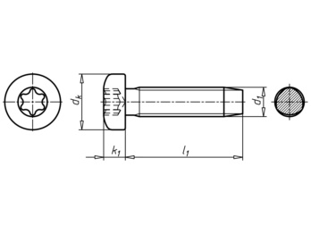
GEFU® thread-rolling screw With Taptite 2000® thread, flat head and hexalobular drive
GEFU DIN 7500-1 steel zinc plated flat head TX
SCR-PANHD-DIN7500-PE-TX45-(A2K)-M8,0X40


Register now and access more than 125,000 products
Self-tapping screws form a nut thread in cast blind holes, rim holes and drilled, lasered and punched sheet metal parts. Unlike thread cutting, self-tapping does not interrupt the material structure in the receiving thread. Instead, the material is displaced and strain-hardened.
Benefits:
Cost savings
- Eliminates thread cutting
Non-cutting thread formation
Low rolling torques with greater thread flank overlap
- TRILOBULAR shape of the core diameter combined with the radius profile of the thread flanks
High clamping force
- Due to low rolling torques
High load-bearing capacity
- Due to large thread flank overlap
- Due to strain-hardened counter thread (nut thread)
Protection against loss (reduced likelihood of screw working loose)
- Play-free and self-locking thread seating
The formed thread corresponds to a standard metric thread
- Where necessary, the GEFU screw can be replaced with a metric screw.
The suitability of the GEFU
® for the application or component in question must be determined by testing in advance. Guideline values for suitable hole diameters are specified in DIN 7500-2.
Datasheets(X)
CAD data (available after login)
Examples of materials suitable for this type of non-cutting direct screwing are ductile materials such as steel (up to approx. 500 N/mm²), die-cast zinc, aluminium, copper, copper alloys etc.
 | |
Thread type x nominal diameter (d1) | M8 |
Length (l1) | 40 mm |
Head diameter (dk) | 16 mm |
Head height (k1) | 6 mm |
Head type | Flat head |
Material | Steel, case-hardened |
Surface | Zinc plated |
Thread type | Metric thread |
Internal drive | TX45 |
Guideline values for hole diameters | 7.4 mm |
Standards | DIN 7500-1 |
RoHS-compliant | Yes |


