Hollow-ceiling anchor W-HD
Hollow-ceiling anchor W-HD
ANC-(W-HD)-(A2K)-M6X30/40
Art.-no. 0905120601
EAN 4046778646312


Register now and access more than 125,000 products
- Screws or threaded rods can be used
- The anchor can also be mounted outside the cavity axis, up to 50 mm from the prestressed strand – maximum flexibility
- Quick, easy installation – no special tool required
- Immediate load-bearing capacity – no waiting
- DIBt National technical approval Z-21.1-1832
- Fire resistance (base material: concrete C45/55 or C50/60): R30, R60, R90, R120: DIBt National technical approval Z-21.1-1832, fire protection test report no. (3526/3426)
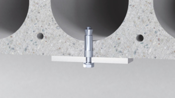
- The cone is separated from the expansion sleeve when the screw or hexagon nut is tightened. - Important: At least three screw/nut rotations are required. Applying the installation torque pulls the cone into the expansion sleeve and expands it
- Anchoring is only permissible in hollow-core prestressed concrete ceilings with a hollow space width that does not exceed 4.2 times the web width (bH <= 4.2 x bSt)
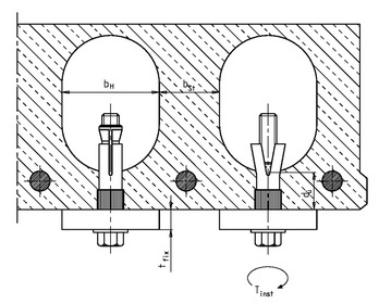
Key:
tfi x = thickness of the attachment
du = mirror thickness
bH = cavity width
bSt = web width
sSp = axis distance to pre-stressed strand
c = edge distance
Tinst = installation torque
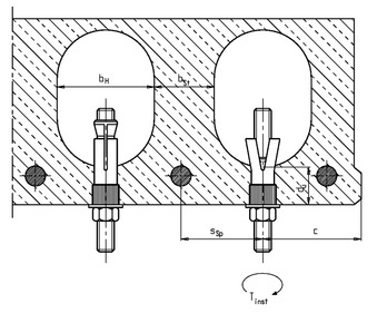
Key:
tfi x = thickness of the attachment
du = mirror thickness
bH = cavity width
bSt = web width
sSp = axis distance to pre-stressed strand
c = edge distance
Tinst = installation torque
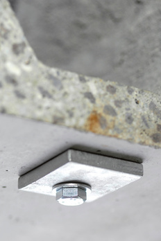
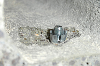
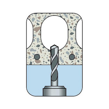
Create the drill hole
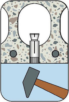
Set anchor in place
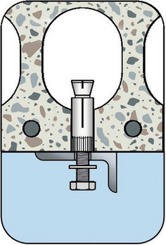
Mount component
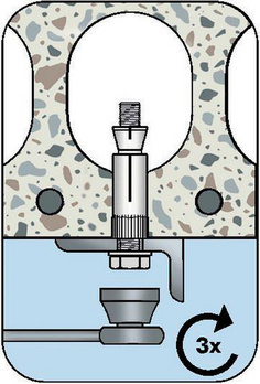
At least three rotations of the screw - Cone separates from sleeve
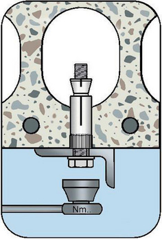
Apply installation torque
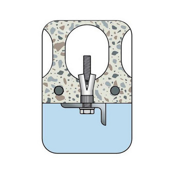
Installation status
Datasheets(X)
CAD data (available after login)
Special fastener for anchoring in hollow-core prestressed concrete ceilings
Suitable for cavities and solid zones of hollow-core prestressed concrete ceilings
Fixing points and anchors in a redundant non-structural system with approval
- Hollow-core prestressed concrete ceilings with concrete compressive strength class of C45/55 or B55
- E.g. anchoring of lightweight ceiling coverings and suspended ceilings as well as for statically comparable anchoring up to 1.0 kN/sqm and the mounting of metal structures, brackets, cable conduits, pipes, ventilation lines, suspended ceilings etc.
W-HD can be used in dry indoor areas, e.g. homes, offices, schools, hospitals, retail outlets
Anchor diameter | 6 mm |
Sleeve length | 30 mm |
Required screw length (l s) | 42 mm + thickness of the add-on part (t fix) |
Required stud-bolt length (l B) | 47 + thickness of the add-on part (t fix) |
Nominal drill-bit diameter (d 0) | 10 mm |
Drill hole depth (h 0) | 50 mm |
Through-hole in the component to be connected (d f) | 7 mm |
Installation torque (T inst) | 10 Nm |
Material | Steel |
Surface | Zinc plated |
| Performance data | ||||||||||||||||||
| (Fire resistance R30, R60, R90, R120 see fire protection test report no. 3526/3426) and gen. construction permit perm. no.: Z-21.1-1832 | ||||||||||||||||||
| Anchor diameter [mm] | M6 | M8 | M10 | M12 | ||||||||||||||
| Mirror thickness | du ≥ [mm] | 25 | 30 | 40 | 50 | 25 | 30 | 40 | 50 | 25 | 30 | 40 | 50 | 25 | 30 | 40 | 50 | |
| Spacing between individual anchors or anchor pairs | scr ≥ [mm] | 300 | ||||||||||||||||
| Individual anchors | ||||||||||||||||||
| Admissible load Tensile, shear load and diagonal tensile force at every angle | Admissible load1)2) Prestressed concrete hollow-core panels edge distance ccr ≥ 150 mm Spacing scr ≥ 300 mm | Fadm [kN] ≥ C45/551)2) | 0,7 | 0,9 | 2,0 | 2,9 | 0,7 | 0,9 | 2,0 | 3,6 | 0,9 | 1,2 | 3,0 | 3,6 | 1,0 | 1,2 | 3,0 | 4,3 |
| ccr ≥ [mm] | 150 | |||||||||||||||||
| Admissible load1)2) Prestressed concrete hollow-core panels min. edge distance cmin ≥ 100 mm Spacing scr ≥ 300 mm | Fadm [kN] ≥ C45/551)2) | 0,35 | 0,8 | 1,8 | 2,4 | 0,35 | 0,8 | 1,8 | 3,0 | 0,8 | 1,0 | 2,7 | 3,0 | 0,8 | 1,0 | 2,7 | 3,6 | |
| cmin ≥ [mm] | 100 | |||||||||||||||||
| Anchor pair3) | ||||||||||||||||||
| Admissible load Tensile, shear load and diagonal tensile force at every angle | Admissible load1)2) Prestressed concrete hollow-core panels edge distance ccr ≥ 150 mm Min. spacing smin | Fadm/anchor pair [kN] ≥ C45/551)2) | 0,7 | 1,4 | 2,6 | 3,9 | 0,7 | 1,4 | 2,6 | 4,8 | 1,1 | 2,0 | 4,8 | 4,8 | 1,2 | 2,0 | 4,8 | 5,7 |
| smin ≥ [mm] | 70 | 80 | 100 | 100 | 70 | 80 | 100 | 100 | 70 | 80 | 100 | 100 | 70 | 80 | 100 | 100 | ||
| ccr ≥ [mm] | 150 | |||||||||||||||||
| Admissible load1)2) Prestressed concrete hollow-core panels edge distance cmin ≥ 100 mm Min. spacing smin | Fadm/anchor pair [kN] ≥ C45/551)2) | 0,35 | 1,25 | 2,35 | 3,2 | 0,35 | 1,25 | 2,35 | 4 | 0,9 | 1,8 | 4,3 | 4,3 | 1 | 1,8 | 4,3 | 4,8 | |
| smin ≥ [mm] | 70 | 80 | 100 | 100 | 70 | 80 | 100 | 100 | 70 | 80 | 100 | 100 | 70 | 80 | 100 | 100 | ||
| cmin ≥ [mm] | 100 | |||||||||||||||||
| Admissible bending moment strength class 5.8 | Madm [Nm] | - | 10,7 | 21,4 | 37,4 | |||||||||||||
| Admissible bending moment strength class 8.8 | Madm [Nm] | 4,4 | 17,1 | 34,2 | 59,8 | |||||||||||||
| 1) When introducing external loads into the hollow prestressed concrete panel ceiling via anchors, the shear carrying capacity must be reduced. When fastening light ceiling coverings and joist constructions in accordance with DIN 18168-1:1981-10, this reduction is not necessary. 2) For edge distances cmin ≤ c ≤ ccr, the admissible loads may be determined via linear interpolation. 3) The admissible loads apply to the anchor pair. The admissible load for the anchor with the greatest load may not exceed the values specified for the individual anchors. For anchors in an anchor pair with spacings of smin ≤ s ≤ scr , the admissible load may be linearly interpolated, whereby twice the admissible load for individual anchors may be applied to the anchor pair with centric load transfer for the ultimate limit when s = scr. | ||||||||||||||||||
| Characteristic values | |||||
| Nominal drill diameter4) | d0 [mm] | 10 | 12 | 16 | 18 |
| Diameter of cutting edges4) | dcut ≤ [mm] | 10,45 | 12,5 | 16,5 | 18,5 |
| Drill hole depth | h0 [mm] | 50 | 55 | 60 | 70 |
| Through hole in the component being connected | df ≤ [mm] | 7 | 9 | 12 | 14 |
| Installation torque | Tinst = [Nm] | 10 | 20 | 30 | 40 |


