JB-D window installation rail with screw-on plate
JB-D mounting rail with mounting plate
MNTRL-JB-D50-40-AM8-(A2K)
Art.-no. 047973356
EAN 4049557173740
Register now and access more than 125,000 products
Systematic, flexible, secure
The JB-D adjustable window installation system enables glazing to be installed systematically, in line with RAL guidelines and with safe transfer of all live loads. The system is adjustable in three dimensions to enable easy compensation of structural tolerances. It can be installed at any level and adjusted according to the isothermal profile.
The load capacity of brackets and rails has been determined by the manufacturer based on test report no. 10541805 from IfT Rosenheim. Individual calculations can be found in the guidelines on installing windows and house doors.
- Please check the properties and conditions of all brackets and rails when using fasteners!
- Load-bearing capacity must always be calculated using 2 brackets! Overview of the window mounting rail load-bearing capacity with compressive + tensile forces


Datasheets(X)
- Solid sand-lime brick, aerated concrete, concrete and perforated brick masonry
- For lateral attachment of windows to building structures
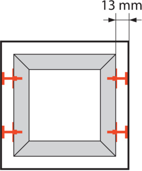
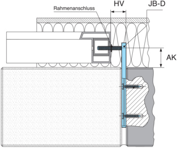
The mounting rails can be mounted on the window frame profile in the pre-drilled blind or through holes (Ø 10.5 mm) either during window production or later on the building site. Once the windows have been positioned on the brackets and aligned, the mounting rails can be unscrewed until the sides are flush with the wall (masonry). Align the window vertically and secure it in place.
Type description | JB-D50/5-G-40 |
Max. projection | 50 mm |
Max. load force | 600 N |
Length | 138 mm |
Width | 37.5 mm |
Max. distance adjustment | 40 mm |
Surface | Zinc plated |
Material | Steel |
| Overview of load-bearing capacity of the JB-D window installation rail | ||||||||||||||||
| Product | Load type | Load-bearing capacity in Newton | ||||||||||||||
| Side mounting is calculated with 2 rails! | Tensile stress (H1)/(H2) | 250 | 225 | 200 | ||||||||||||
| + | Pressure H1/H2 | 540 | 480 | 400 | ||||||||||||
| JB-D50/5 | Tensile stress + pressure | 790 | 705 | 600 | ||||||||||||
| Tensile stress (H1)/(H2) | 900 | 750 | 600 | |||||||||||||
| + | Pressure H1/H2 | 2000 | 1500 | 1000 | ||||||||||||
| JB-D50/10 | Tensile stress + pressure | 2900 | 2250 | 1600 | ||||||||||||
| Tensile stress (H1)/(H2) | 600 | 520 | 440 | 350 | 300 | 250 | ||||||||||
| + | Pressure H1/H2 | 1350 | 1140 | 920 | 700 | 600 | 500 | |||||||||
| JB-D100/10 | Tensile stress + pressure | 1950 | 1660 | 1360 | 1050 | 900 | 750 | |||||||||
| Tensile stress (H1)/(H2) | 250 | 215 | 175 | 140 | 120 | 100 | ||||||||||
| + | Pressure H1/H2 | 450 | 385 | 315 | 250 | 225 | 200 | |||||||||
| JB-D150/10 | Tensile stress + pressure | 700 | 600 | 490 | 390 | 345 | 300 | |||||||||
| Tensile stress (H1)/(H2) | 250 | 215 | 175 | 140 | 120 | 100 | ||||||||||
| + | Pressure H1/H2 | 1200 | 1050 | 900 | 750 | 625 | 500 | |||||||||
| JB-D150/10-AW75 | Tensile stress + pressure | 1450 | 1265 | 1075 | 890 | 745 | 600 | |||||||||
| Projection in mm | 20 | 30 | 40 | 50 | 60 | 70 | 80 | 90 | 100 | 110 | 120 | 130 | 140 | 150 | ||
| Calculation with 2 brackets for tensile stress + pressure | ||||||||||||||||


