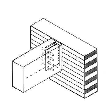
Joist bracket
Beam bearer
BMBEAR-H200MM
Register now and access more than 125,000 products
- Easy on-site installation thanks to mounting slot in joist bracket blade
- Sheet metal hot-dip galvanised on both sides (S250GD +Z275 (approx. 20 µm)), thickness 3.0 mm in line with EN 10327:2004
- Application in utilisation classes 1 and 2 in line with EN 1995:2013
ETA-09/0105
The secondary beam can be mounted on the joist bracket attached to the main beam after the first dowel pin has been driven in to the uppermost hole in the secondary beam. To do this, the secondary beam with the uppermost dowel pin mounted in the slot area is hooked into the blade area of the joist bracket from above.
The secondary beam should be approx. 40 mm taller than the joist bracket. If the bracket is 90 mm in height, a secondary beam 100 mm in height can be used.
The diameter of the dowel pin may only be max. 0.5 mm (d = 8 mm) or 1.0 mm (d = 12 mm) smaller than the diameter of the hole.
Available work documents:
Load tables and detailed processing instructions can be found on the service page www.wuerth.de/holzverbinder.
Datasheets(X)
Load-bearing connections of timber joists to timber main beams or posts in visible areas
Suitable fasteners:
- Ribbed nail in line with EN 14592: 4.0x40 mm
- Dowel pin in line with EN 14592, d = 8, 12 mm
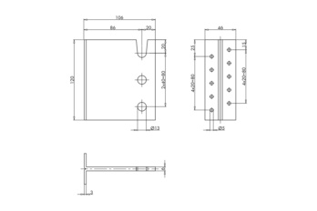
Width x height x depth | 46 x 200 x 106 mm |
Min. joist hanger height | 240 mm |
Hole diameter in subcarrier nJ/main carrier nH | 13 / 5 mm |
Number of holes in subcarrier nJ/main carrier nH | 5 / 19 PCS |
Weight | 1099 g |
Approval | ETA-09/0105 |
Thickness | 3 mm |
Material | Steel |
Material designation | DX51D |
Material standard | DIN EN 10327:2004 |
Surface | Hot dip galvanized |
Characteristic load-bearing capacities in kN with Würth joist bracket according to ETA-09/0105, secondary beam width 60 mm | ||||||
Characteristic load-bearing capacities Würth joist bracket, solid wood C24 according to DIN 380 (Ƥk = 350 kg/m³), secondary beam width 60 mm | ||||||
Art. no. | Joist bracket height in mm | Complete nailing with Würth comb/anchor nails | Minimum width/height in mm | |||
Fz,down,Rk | Fz,up,Rk | |||||
4 x 40mm | 4 x 60mm | 4 x 40mm | 4 x 60mm | |||
0681 350 90 | 90 | 3,57 | 5,79 | 4,63 | 7,4 | 60/130 (100) |
0681 350 120 | 120 | 11,02 | 11,02 | 7,06 | 7,06 | 60/160 |
0681 350 160 | 160 | 17,76 | 17,76 | 13,48 | 13,48 | 60/200 |
0681 350 200 | 200 | 25,67 | 25,67 | 20,3 | 21,39 | 60/240 |
0681 350 240 | 240 | 33,65 | 34,44 | 27,36 | 30,38 | 60/280 |
Characteristic load-bearing capacities Würth joist bracket, glued laminated timber GL 24h according to DIN EN 14080 (Ƥk = 385 kg/m³), secondary beam width 60 mm | ||||||
Art. no. | Joist bracket height in mm | Complete nailing with Würth comb/anchor nails | Minimum width/height in mm | |||
Fz,down,Rk | Fz,up,Rk | |||||
4 x 40mm | 4 x 60mm | 4 x 40mm | 4 x 60mm | |||
0681 350 90 | 90 | 4,17 | 6,70 | 5,39 | 8,50 | 60/130 (100) |
0681 350 120 | 120 | 12,12 | 12,12 | 7,77 | 7,77 | 60/160 |
0681 350 160 | 160 | 19,53 | 19,53 | 14,83 | 14,83 | 60/200 |
0681 350 200 | 200 | 28,24 | 28,24 | 22,96 | 23,53 | 60/240 |
0681 350 240 | 240 | 36,94 | 37,89 | 30,71 | 33,42 | 60/280 |
Factor table for design value: | ||||||
NKL | Continuously | Long | Medium | Short | Short/very short | Very short |
1 and 2 | 0,462 | 0,538 | 0,615 | 0,692 | 0,769 | 0,846 |
Notes:
Mex = F x (width HT/2 + 40mm) These are guides for planning purposes. The values must be calculated for each project by authorised persons. |
Characteristic load-bearing capacities in kN with Würth joist bracket according to ETA-09/0105, secondary beam width 100 mm | ||||||
Characteristic load-bearing capacities Würth joist bracket, solid wood C24 according to DIN 380 (Ƥk = 350 kg/m³), secondary beam width 100 mm | ||||||
Art. no. | Joist bracket height in mm | Complete nailing with Würth comb/anchor nails | Minimum width/height in mm | |||
Fz,down,Rk | Fz,up,Rk | |||||
4 x 40mm | 4 x 60mm | 4 x 40mm | 4 x 60mm | |||
0681 350 90 | 90 | 3,57 | 5,79 | 4,63 | 7,4 | 100/130 (100) |
0681 350 120 | 120 | 12,03 | 17,2 | 7,7 | 11,23 | 100/160 |
0681 350 160 | 160 | 19,23 | 26,46 | 13,63 | 20,42 | 100/200 |
0681 350 200 | 200 | 26,47 | 35,61 | 20,3 | 29,48 | 100/240 |
0681 350 240 | 240 | 33,65 | 44,65 | 27,36 | 38,76 | 100/280 |
Characteristic load-bearing capacities Würth joist bracket, glued laminated timber GL 24h according to DIN EN 14080 (Ƥk = 385 kg/m³), secondary beam width 100 mm | ||||||
Art. no. | Joist bracket height in mm | Complete nailing with Würth comb/anchor nails | Minimum width/height in mm | |||
Fz,down,Rk | Fz,up,Rk | |||||
4 x 40mm | 4 x 60mm | 4 x 40mm | 4 x 60mm | |||
0681 350 90 | 90 | 4,17 | 6,70 | 5,39 | 8,50 | 100/130 (100) |
0681 350 120 | 120 | 13,52 | 18,38 | 8,88 | 11,78 | 100/160 |
0681 350 160 | 160 | 21,37 | 28,65 | 15,57 | 22,49 | 100/200 |
0681 350 200 | 200 | 29,20 | 38,30 | 22,96 | 32,51 | 100/240 |
0681 350 240 | 240 | 36,94 | 47,82 | 30,71 | 42,38 | 100/280 |
Factor table for design value: | ||||||
NKL | Continuously | Long | Medium | Short | Short/very short | Very short |
1 and 2 | 0,462 | 0,538 | 0,615 | 0,692 | 0,769 | 0,846 |
Notes: The measurement tables can only be used if all nails and rod anchors are inserted into the intended holes. The secondary beam should be about 40 mm greater in height than the joist bracket. The load-bearing capacities of the respective fasteners are determined in accordance with DIN EN 1995-1-1/NA. The force Fz,down and Fz,up act in the centre of the secondary beam. The main support must be secured to prevent torsion. The gap between the main support and the secondary beam must not exceed 8 mm. The transverse tensile capacity of the main support must be investigated separately. If necessary, a transverse tension reinforcement with ASSY plus FT screws must be used. For one-sided connections on the main support, the offset moment must be taken into account. The regulations of ETA-09/0105 must be applied. Mex = F x (width HT/2 + 40mm) These are guides for planning purposes. The values must be calculated for each project by authorised persons. |
Characteristic load-bearing capacities in kN with Würth joist bracket according to ETA-09/0105, secondary beam width 80 mm | ||||||
Characteristic load-bearing capacities Würth joist bracket, solid wood C24 according to DIN 380 (Ƥk = 350 kg/m³), secondary beam width 80 mm | ||||||
Art. no. | Joist bracket height in mm | Complete nailing with Würth comb/anchor nails | Minimum width/height in mm | |||
Fz,down,Rk | Fz,up,Rk | |||||
4 x 40mm | 4 x 60mm | 4 x 40mm | 4 x 60mm | |||
0681 350 90 | 90 | 3,57 | 5,79 | 4,63 | 7,4 | 80/130 (100) |
0681 350 120 | 120 | 12,03 | 15,1 | 7,7 | 9,67 | 80/160 |
0681 350 160 | 160 | 19,23 | 24,33 | 13,63 | 18,47 | 80/200 |
0681 350 200 | 200 | 26,47 | 35,18 | 20,3 | 29,32 | 80/240 |
0681 350 240 | 240 | 33,65 | 44,65 | 27,36 | 38,76 | 80/280 |
Characteristic load-bearing capacities Würth joist bracket, glued laminated timber GL 24h according to DIN EN 14080 (Ƥk = 385 kg/m³), secondary beam width 80 mm | ||||||
Art. no. | Joist bracket height in mm | Complete nailing with Würth comb/anchor nails | Minimum width/height in mm | |||
Fz,down,Rk | Fz,up,Rk | |||||
4 x 40mm | 4 x 60mm | 4 x 40mm | 4 x 60mm | |||
0681 350 90 | 90 | 4,17 | 6,70 | 5,39 | 8,50 | 80/130 (100) |
0681 350 120 | 120 | 13,54 | 16,61 | 8,88 | 10,64 | 80/160 |
0681 350 160 | 160 | 21,37 | 26,77 | 15,57 | 20,32 | 80/200 |
0681 350 200 | 200 | 29,20 | 38,30 | 22,96 | 32,25 | 80/240 |
0681 350 240 | 240 | 36,94 | 47,82 | 30,71 | 42,38 | 80/280 |
Factor table for design value: | ||||||
NKL | Continuously | Long | Medium | Short | Short/very short | Very short |
1 and 2 | 0,462 | 0,538 | 0,615 | 0,692 | 0,769 | 0,846 |
Notes: The measurement tables can only be used if all nails and rod anchors are inserted into the intended holes. The secondary beam should be about 40 mm greater in height than the joist bracket. The load-bearing capacities of the respective fasteners are determined in accordance with DIN EN 1995-1-1/NA. The force Fz,down and Fz,up act in the centre of the secondary beam. The main support must be secured to prevent torsion. The gap between the main support and the secondary beam must not exceed 8 mm. The transverse tensile capacity of the main support must be investigated separately. If necessary, a transverse tension reinforcement with ASSY plus FT screws must be used. For one-sided connections on the main support, the offset moment must be taken into account. The regulations of ETA-09/0105 must be applied. Mex = F x (width HT/2 + 40mm) These are guides for planning purposes. The values must be calculated for each project by authorised persons. |
Select RAL-colour code
!! NOTE: On-screen visualisation of the colour differs from real colour shade!!