Tension anchor V plus
Tension anchor, V plus
TENSANC-VPLUS-560X90X65X4,0MM
Art.-no. 5392000257
EAN 4053479327273

Register now and access more than 125,000 products
- Extremely high load-carrying capacities
- Large base plate for optimised force initiation into the floor
- Indirect mounting (max. 26 mm) via an intermediate layer (e.g. OSB)
- Extra-long back panel for optimum placing of the number of screws/nails required, while complying with the requisite edging on the wooden stand
- Sheet metal hot-dip galvanised on both sides (DD11+ Z 275) in line with EN 10025-2:2004 3.0 or 4.0 mm in thickness
- Application in utilisation classes 1 and 2 in line with EN 1995:2013
CE labelling as per European Technical Approval ETA-14/0274
- The respective permissible edge distances and spacings of the fasteners must be observed
Datasheets(X)
Base anchoring of supports, roof beams, timber frame constructions or solid wood elements.
Suitable fasteners:
- Ring-shank/grooved nails in accordance with EN 14592: 4.0 x 40 to 100 mm
- ASSY 4.0 joist hanger screw in accordance with ETA-11/0190 or EN 14592
- Bolts in accordance with manufacturers' specifications
- Recommended anchors for fastening in concrete: W-BS; W-FAZ; W-VIZ; WIT-VM 250; WIT-UH 300
- The respective permissible edge distances and spacings of the fasteners must be observed.
 | |
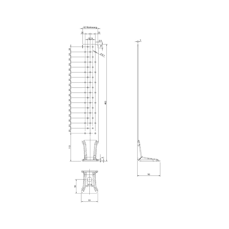
Width x height x depth | 65 x 560 x 90 mm |
Baseplate thickness | 8 mm |
Thickness | 4 mm |
Hole diameter in subcarrier nJ/main carrier nH | 5.1 / 18 mm |
Number of holes in subcarrier nJ + main carrier nH | 57 + 1 PCS |
Weight | 1540 g |
Approval | ETA-14/0274 |
Distance between support and centre of hole | 35 mm |
Min. handle width | 60 mm |
Recommended type of anchor | W-VM250; W-FAZ |
Material | Sheet steel |
Material designation | DD11 |
Material standard | EN 10025- 2:2004 |
Surface | Hot dip galvanized |
| Overview of load capacity tables for HTA and Vplus tension anchors | Characteristic load capacity and design value of the load-bearing capacity ("short") in load case F1 for Würth tension anchor HTA and Vplus in accordance to ETA 14/0274 | Tension anchor connection HTA and Vplus - without intermediate layer | Type | Size in mm | U-washer/base plate | KLED | Load capacity per fastener (ring-shank nail or joist hanger screw in mm) in kN | Load capacity steel in kN | Coefficient kt | 4x40 | 4x50 | 4x60 | 5x35 | 5x40 | 5x50 |
| Vplus | Lx90x65x3.0 | without specification | char. | FVM,Rk = | 1,57 | 1,87 | 1,93 | 1,88 | 2,14 | 2,29 | FS,Rk = | 36,2 | 1,0 |
| short | FVM,Rd = | 1,08 | 1,30 | 1,34 | 1,30 | 1,48 | 1,59 | FS,Rd = | 29 | ||||
| Lx90x65x4.0 | without specification | char. | FVM,Rk = | 1,57 | 1,87 | 1,93 | 1,88 | 2,14 | 2,29 | FS,Rk = | 48,3 | 1,0 | |
| short | FVM,Rd = | 1,08 | 1,30 | 1,34 | 1,30 | 1,48 | 1,59 | FS,Rd = | 38,6 | ||||
| HTA | Lx60x60x3.0 | U-washer 30x3 mm | char. | FVM,Rk = | 1,57 | 1,87 | 1,93 | 1,88 | 2,14 | 2,29 | FS,Rk = | 32,5 | 1,1 |
| short | FVM,Rd = | 1,08 | 1,30 | 1,34 | 1,30 | 1,48 | 1,59 | FS,Rd = | 26 | ||||
| Lx60x60x3.0 | Base plate 10 mm | char. | FVM,Rk = | 1,57 | 1,87 | 1,93 | 1,88 | 2,14 | 2,29 | FS,Rk = | 45 | 1,1 | |
| short | FVM,Rd = | 1,08 | 1,30 | 1,34 | 1,30 | 1,48 | 1,59 | FS,Rd = | 36 | ||||
| Lx80x80x3.0 | U-washer 37x3 mm | char. | FVM,Rk = | 1,57 | 1,87 | 1,93 | 1,88 | 2,14 | 2,29 | FS,Rk = | 60 | 1,1 | |
| short | FVM,Rd = | 1,08 | 1,30 | 1,34 | 1,30 | 1,48 | 1,59 | FS,Rd = | 48 | 1,1 | |||
| Tensile force in anchor bolt: FB,Ed = kt x FEd | |||||||||||||
Notes:
| |||||||||||||
Select RAL-colour code
!! NOTE: On-screen visualisation of the colour differs from real colour shade!!


