


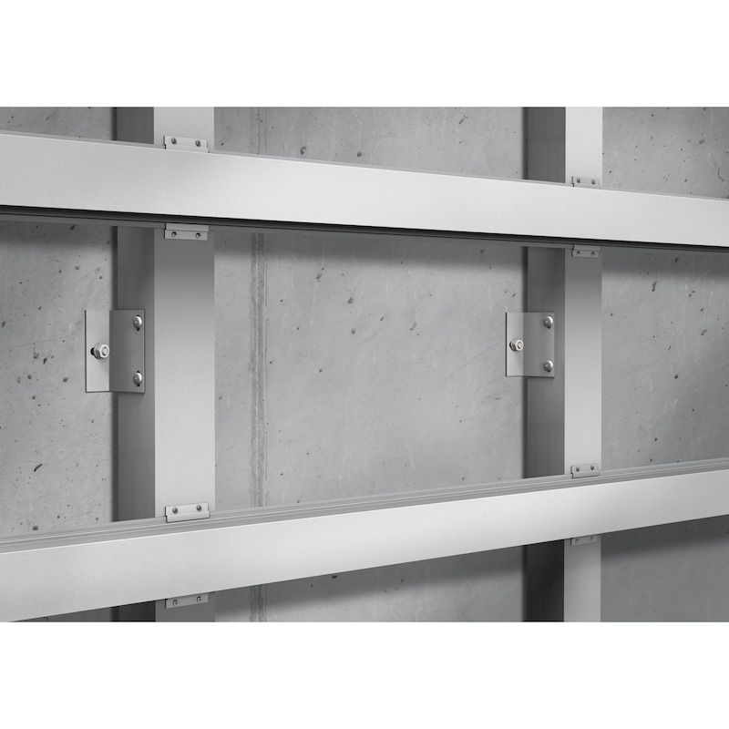


W-FAZ PRO/S Zinc plated steel
ANC-(W-FAZ PRO/S)-(A2K)-0-40-M12X115
Art.-no. 5930212020
EAN 4062856404377


Register now and access more than 125,000 products
- Highest loads at low spacing and edge distances: Large embedment depths enable a particularly high load capacity per anchor - even at reduced spacing and edge distances.
- Quick installation, minimum effort: Extra-low embedment depths reduce drilling and embedment time and reduce the risk of reinforcement hits.
- Economical and versatile: The freely selectable embedment depth enables optimum utilisation of the anchor - tailored to the application, load requirements and structural conditions.
- Ideal for fastening close to edges: Minimal spacing and edge distances allow compact anchor plates as well as secure fastenings close to the concrete edge and in thin concrete members.
- For applications subject to seismic activity: High performance under seismic activity - suitable for seismic performance categories C1 and C2.
European technical assessment ETA-20/0229 for single fixing point, option 1, cracked and uncracked concrete
- Static or quasi-static loads.
- Seismic activity, performance categories C1 and C2.
- Fire resistance R30, R60, R90, R120.
Approved base materials
- Cracked or uncracked concrete with a concrete compressive strength of C20/25 to C50/60 and C50/60 to C80/95.
- Compressed, reinforced and non-reinforced normal weight concrete without fibres.
- Steel fibre reinforced concrete (SFRC) with a concrete compressive strength of C20/25 to C50/60.
Load-bearing behaviour and fire exposure (standard time-temperature curve) - expert report no. GS 6.1/20-018-1
- Fire duration 180 minutes (M8-M16).
Swiss Federal Office for Civil Protection (Bundesamt für Bevölkerungsschutz, BABS) - Approval for shock testing BZS D 20-602
- Use in Swiss civil protection buildings (M8-M16, from standard anchorage depth hef,std).
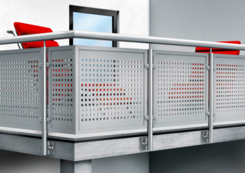 Fastening of railings
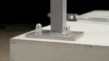
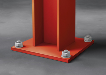 Heavy steel structures
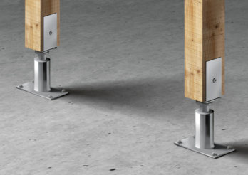 Post support bracket
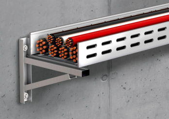
Cable trays
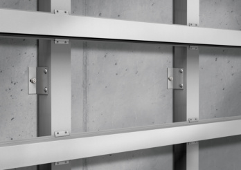 Metal substructures
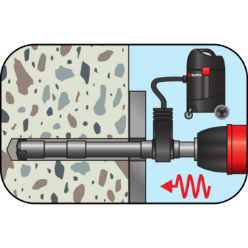
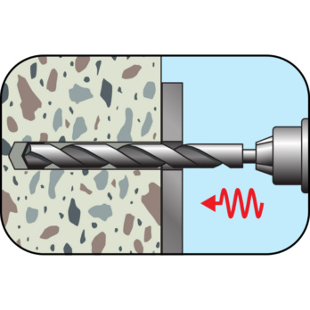
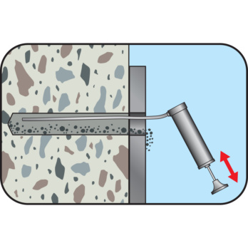
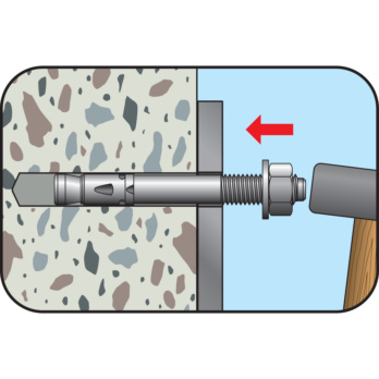
Datasheets(X)

For use as single fixing point or anchors in a redundant non-structural system with approval
- In normal weight concrete C20/25 to C50/60 (cracked and uncracked concrete).
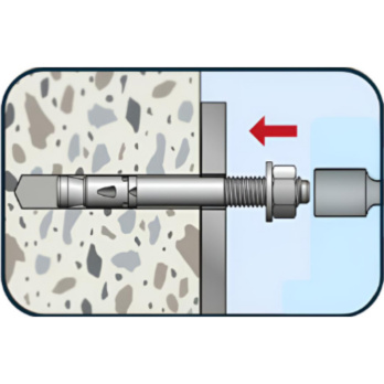
- Suitable for pre-positioned installation, in-place installation and stand-off installation.
Suitable for anchoring medium to heavy loads in concrete
Fastening of e.g. metal structures, supports, steel beams, brackets, railings, cable conduits, pipe conduits, wooden structures, beams, joist brackets etc.
Fastenings subject to seismic activity in earthquake-prone areas.
Fastenings subject to fire exposure.
The W-FAZ PRO/S (galvanised steel) may only be used in dry indoor areas.
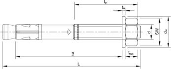 | |
Metric anchor diameter | M12 |
Anchor length (l) | 115 mm |
Min./max. height of the fixture (t fix) | 0-40 mm |
Attachment height standard (t fix,std) | 20 mm |
Min. effective anchoring depth (h ef, min) | 50 mm |
Max. effective anchoring depth (h ef, max) | 90 mm |
Effective anchoring depth Standard (h ef, std) | 70 mm |
Usable length (B) | 90 mm |
Attachment height variable (t fix ,var) | B - hef |
Disc diameter x disc thickness | 24 x 2.5 mm |
Width across flats | 19 mm |
Nominal drill-bit diameter (d 0) | 12 mm |
Drill hole depth variable (h 0, var) | hef + 10 |
Min. drill hole depth (h 0, min) | 60 mm |
Max. drill hole depth (h 0, max) | 100 mm |
Drill hole depth Standard (h 0, std) | 80 mm |
Material | Steel |
Surface | Zinc plated |
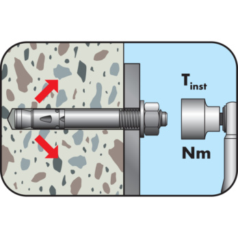
Torque during anchoring (T inst) | 60 Nm |
Through-hole in the component to be connected (d f) | 14 mm |
Thread type x anchor diameter x thread length (L th) | M12 x 60 |
Bolt protrusion (C) | 16.0 mm |
Approval | ETA-20/0229 |
Seismology C1 | Yes |
Seismology C2 | Yes |
| Performance data1) on an individual anchor without the influence of the edge distance | Anchor diameter | [mm] | M8 | M10 | M12 | M16 | ||||||||
| Variable effective anchorage depth | hef,var | [mm] | The effective anchorage depth can be set to anywhere between hef,min and hef,max. The Würth Technical Software can help you with the calculation. | |||||||||||
| hef,min | hef,max | hef,std | hef,min | hef,max | hef,std | hef,min | hef,max | hef,std | hef,min | hef,max | hef,std | |||
| 352) | 90 | 45 | 40 | 100 | 60 | 50 | 125 | 70 | 65 | 160 | 85 | |||
| in cracked concrete | ||||||||||||||
| Admissible centric tension load in concrete C 20/253) | Nadm | [kN] | 3,5 | 4,5 | 4,5 | 4,3 | 7,1 | 7,1 | 6,1 | 10,5 | 10,0 | 9,0 | 14,3 | 13,4 |
| Admissible shear load in concrete C 20/253) | Vadm | [kN] | 9,0 | 9,0 | 9,0 | 13,4 | 15,3 | 15,3 | 18,2 | 21,9 | 21,9 | 32,3 | 34,3 | 34,3 |
| Admissible bending moment | Madm | [Nm] | 17,1 | 34,3 | 60,0 | 137,1 | ||||||||
| in uncracked concrete | ||||||||||||||
| Admissible centric tension load in concrete C 20/253) | Nadm | [kN] | 5,0 | 6,7 | 6,7 | 6,1 | 11,4 | 11,2 | 8,5 | 14,3 | 14,1 | 12,6 | 23,8 | 18,8 |
| Admissible shear load in concrete C 20/253) | Vadm | [kN] | 9,0 | 15,3 | 21,9 | 34,3 | ||||||||
| Admissible bending moment | Madm | [Nm] | 17,1 | 34,3 | 60,0 | 137,1 | ||||||||
| Admissible load when exposed to fire (R30, R60, R90, R120), see European Technical Assessment ETA-20/0229 | ||||||||||||||
| Admissible load when exposed to fire (F180) according to the uniform temperature curve based on TR20, see expert report no. GS 6.1/20-018-1 | ||||||||||||||
| 1) The partial safety factors of the resistances stipulated in the ETA and a partial safety factor of the action of γF = 1.4 have been taken into account. Please refer to the European Technical Assessment ETA-20/0229 for information on combining tensile and shear loads, variable effective anchorage depths influenced by edge distances and groups of anchors 2) 2) Use is limited to the anchoring of statically indeterminate systems in dry indoor conditions 3) The concrete has normal reinforcement. Higher values are possible for higher concrete compressive strengths | ||||||||||||||
| Installation parameters1) | ||||||||||
| Anchor diameter | [mm] | M12 | M16 | |||||||
| Variable effective anchorage depths | hef | hef,var | hef,min | hef,max | hef,std | hef,var | hef,min | hef,max | hef,std | |
| [mm] | hef | 50 | 125 | 70 | hef | 65 | 160 | 85 | ||
| Embedment depth | hnom | [mm] | hef+10 | 60 | 135 | 80 | hef+14 | 79 | 174 | 99 |
| Minimum member thicknesses | hmin | [mm] | max (1.5·hef; 100) | 100 | 187,5 | 105 | max (1.5·hef; 120) | 120 | 240 | 127,5 |
| Minimum spacing | smin | [mm] | 50 | 65 | ||||||
| Minimum edge distance | cmin | [mm] | 55 | 65 | ||||||
| Nominal drill ∅ | d0 | [mm] | 12 | 16 | ||||||
| ∅ of cutting edges | dcut ≤ | [mm] | 12,5 | 16,5 | ||||||
| Drill hole depth | h0 | [mm] | hef+10 | 60 | 135 | 80 | hef+14 | 79 | 174 | 99 |
| Through hole in the fixture | df ≤ | [mm] | 14 | 18 | ||||||
| Width across flats | AF | [mm] | 19 | 24 | ||||||
| Torque while installing anchor | Tinst = | [mm] | 60 | 110 | ||||||
| Height of the hexagon nut | tnut | [mm] | 10 | 13 | ||||||
| Height x ∅ of washer | tw x dw | [mm] | 2.5 x 24 | 3 x 30 | ||||||
| 1) For groups of anchors and anchorage close to the edge, the combinations of the minimum values (member thickness, spacing and edge distances) and the associated loads must be determined in accordance with the calculation methods of European Technical Assessment (ETA-20/00229), depending on the effective anchorage depth. | ||||||||||
| Installation parameters1) | ||||||||||
| Anchor diameter | [mm] | M8 | M10 | |||||||
| Variable effective anchorage depths | hef | hef,var | hef,min | hef,max | hef,std | hef,var | hef,min | hef,max | hef,std | |
| [mm] | hef | 35 | 90 | 45 | hef | 40 | 100 | 60 | ||
| Embedment depth | hnom | [mm] | hef+8 | 43 | 98 | 53 | hef+9 | 49 | 109 | 69 |
| Minimum member thicknesses | hmin | [mm] | max (1.5·hef; 80) | 80 | 135 | 80 | max (1.5·hef; 80) | 80 | 150 | 90 |
| Minimum spacing | smin | [mm] | 35 | 40 | ||||||
| Minimum edge distance | cmin | [mm] | 40 | 45 | ||||||
| Nominal drill ∅ | d0 | [mm] | 8 | 10 | ||||||
| ∅ of cutting edges | dcut ≤ | [mm] | 8,45 | 10,45 | ||||||
| Drill hole depth | h0 | [mm] | hef+8 | 43 | 98 | 53 | hef+9 | 49 | 109 | 69 |
| Through hole in the fixture | df ≤ | [mm] | 9 | 12 | ||||||
| Width across flats | AF | [mm] | 13 | 17 | ||||||
| Torque while installing anchor | Tinst = | [Nm] | 15 | 40 | ||||||
| Height of the hexagon nut | tnut | [mm] | 6,5 | 8 | ||||||
| Height x ∅ of washer | tw x dw | [mm] | 1.5 x 16 | 2 x 20 | ||||||
| 1) For groups of anchors and anchorage close to the edge, the combinations of the minimum values (member thickness, spacing and edge distances) and the associated loads must be determined in accordance with the calculation methods of European Technical Assessment (ETA-20/00229), depending on the effective anchorage depth. | ||||||||||
Select RAL-colour code
!! NOTE: On-screen visualisation of the colour differs from real colour shade!!
Last viewed

Hexagon bolt with thread up to the head ISO 4017, steel 8.8, zinc-plated, blue passivated (A2K)

WORKSHOP TOOL TROLLEY FOR ORSY 8.4

Round-headed strip nails, 21°

WÜRTH MODYF Job+ polo shirt

PRO compartment divider set

1/2-inch impact socket wrench insert for hexagon socket screws, metric, long

HDPE UV fold masker

T-handle extraction tool for Henn clamps, swivelling

Screwdriver slotted striking cap with hexagon shank
1/2-inch impact socket wrench insert for hexagon socket screws, metric, long