W-RD plastic frame anchor With collar in natural colour.
Plastic frame anchor, W-RD with collar
ANC-(W-RD)-PLA-W.COLLAR-30-8X100
ZEBRA
Register now and access more than 125,000 products
- Push-through installation
- Immediate load-bearing capacity — no waiting
- Low insertion torque of screw — slight expansion of the anchor, virtually no movement of the anchor sleeve
- Strong twist lock
- Expansion in four directions — high load-bearing capacities
- Improved load transfer: Even, continuous load distribution across the entire expansion area
- The hammer-in stop prevents premature expansion of the anchor during installation
- Anchorage via friction locking and positive locking (perforated brick) between anchor sleeve and anchoring base
- Anchor sleeve made of high-quality polyamide
- Halogen and silicon-free
- Thermally stable from -40°C to +80°C
Performance data determined in Würth test laboratory
Useful information:
Drill perforated and hollow blocks with a rotary drill (without impact mechanism).
Drilling dust must be removed from the drill hole.
Screw length = anchor length + 1 x screw diameter.
Use wood or particle board screws WITHOUT an optimised thread tip (drill bit, counter thread, ring thread etc.).
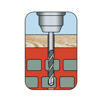 Create the drill hole
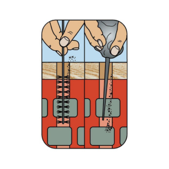 Clean the drill hole
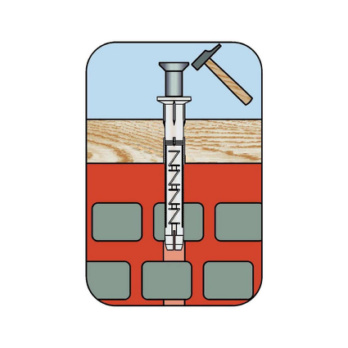
Set anchor and screw
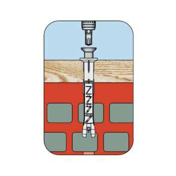
Screw in the screw
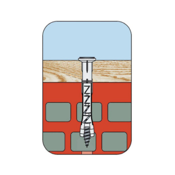
Screw in screw until flush
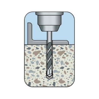 Create the drill hole
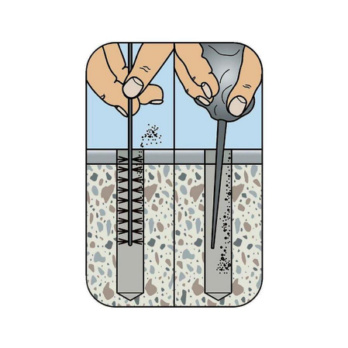 Clean the drill hole
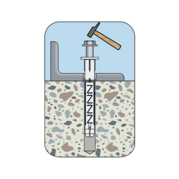
Set anchor and screw
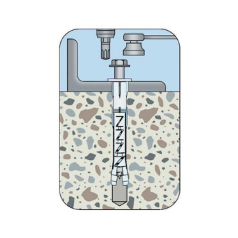
Screw in the screw
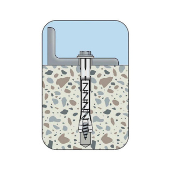
Screw in screw until flush
Datasheets(X)
Secondary attachments: Concrete and masonry made from solid and perforated brick
Universal plastic frame anchor for light and medium loads
W-RD can be anchored in the following anchoring bases: Standard concrete, masonry walls (solid brick, solid sand-lime brick, vertically perforated brick, perforated sand-lime brick, hollow lightweight concrete blocks, solid bricks and blocks made of lightweight concrete)
Installation temperatures: Temperature of anchoring base: ≥ -20°C, temperature of anchor sleeve: ≥ 0°C
Suitable for attaching wardrobes, curtain rails, wall shelves, light wall cupboards, wall-mounted cabinets, mirrors, picture frames, cable clamps, electrical switches, wash basins, wooden beams, wooden slats, metal rails, angle brackets, profiles, signs etc.
For attaching components in conjunction with a wood or particle board screw without an optimised thread tip (e.g. drill tip, counter thread, ring thread etc.)
Can be used outdoors or in wet rooms in conjunction with a stainless steel screw
Anchor diameter | 8 mm |
Anchor length (l) | 100 mm |
Max. attachment height (t fix) | 30 mm |
Nominal drill-bit diameter (d 0) | 8 mm |
Through-hole in the component to be connected (d f) | 8.5 mm |
Screw diameter | 6 mm |
Drill hole depth (h 0) | 80 mm |
Drill hole depth (h 1) | 80 mm |
Type description | W-RD 8, with collar |
| Performance data | ||||||
| Anchor diameter [mm] | 6 | 8 | 8 | 10 | ||
| Anchoring depth hef [mm] | 50 | 50 | 70 | 70 | ||
| Permissible load1) (Tensile, transverse and oblique pull at every angle) | Concrete | Frec [kN] ≥ C20/251) | 0,4 | 0,4 | 0,5 | 0,5 |
| Solid brick Mz, EN 771-1, DIN 105 ≥ NF (≥ 240 x 115 x 71) | Frec [kN] ≥ Mz 361) | 0,2 | 0,3 | 0,4 | 0,3 | |
| Solid sand-lime brick KS, EN 771-2, DIN 106 ≥ NF (≥ 240 x 115 x 71) | Frec [kN] ≥ KS 201) | 0,4 | 0,4 | 0,5 | 0,5 | |
| Solid bricks and solid blocks made of standard concrete EN 771-3, DIN 18153 ≥ NF (≥ 240 x 115 x 71) | Frec [kN] ≥ Vbn121) | 0,4 | 0,4 | 0,6 | 0,6 | |
| Solid bricks and solid blocks made of lightweight concrete EN 771-3, DIN V 18152-100 ≥ NF (≥ 240 x 115 x 71) | Frec [kN] ≥ V41) | 0,1 | 0,2 | 0,3 | 0,3 | |
| Vertically perforated brick HLz, EN 771-1, DIN 105 ≥ 2DF (≥ 240 x 115 x113) | Frec [kN] ≥ Hlz 201) | 0,1 | 0,2 | 0,2 | 0,1 | |
| Hollow sand-lime brick KSL, EN 771-2, DIN 106 ≥ 2DF (≥ 240 x 115 x113) | Frec [kN] ≥ KSL 61) | 0,1 | 0,2 | 0,4 | 0,4 | |
| Hollow block made of lightweight concrete 3K Hbl, EN 771-3, DIN 18151 ≥ 16DF (≥ 497 x 237 x 241) | Frec [kN] ≥ Hbl 61) | 0,1 | 0,2 | 0,1 | 0,3 | |
| 1) The recommended loads were obtained with the plug screw with countersunk head in accordance with DIN 97. | ||||||
Characteristic values | ||||||
Concrete | Axis distance | s ≥ [mm] | 100 | 100 | 100 | 100 |
Edge spacing | c ≥ [mm] | 70 | 70 | 70 | 140 | |
Minimum component thickness | hmin ≥ [mm] | 100 | 100 | 100 | 100 | |
Masonry | Axis distance | s ≥ [mm] | 250 | 250 | 250 | 250 |
Edge spacing | c ≥ [mm] | 100 | 100 | 100 | 100 | |
Minimum component thickness | hmin ≥ [mm] | 115 | 115 | 115 | 115 | |
Nominal drill diameter2) | d0 [mm] | 6 | 8 | 8 | 10 | |
Drill hole depth | h0 ≥ [mm] | 60 | 60 | 80 | 80 | |
Anchoring depth3) | hnom ≥ [mm] | 50 | 50 | 70 | 70 | |
Through hole in component being connected | df ≤ [mm] | 6,5 | 8,5 | 8,5 | 10,5 | |
| 1) The recommended loads were obtained with the plug screw with countersunk head in accordance with DIN 97 (art. no. 0157 0. …). 2) If the drilling hole is created in the perforated brick with impact and hammer action, the load capacity is reduced. 3) The anchors must be positioned in such a way that the spreading part is anchored in the web of the stone. | ||||||


